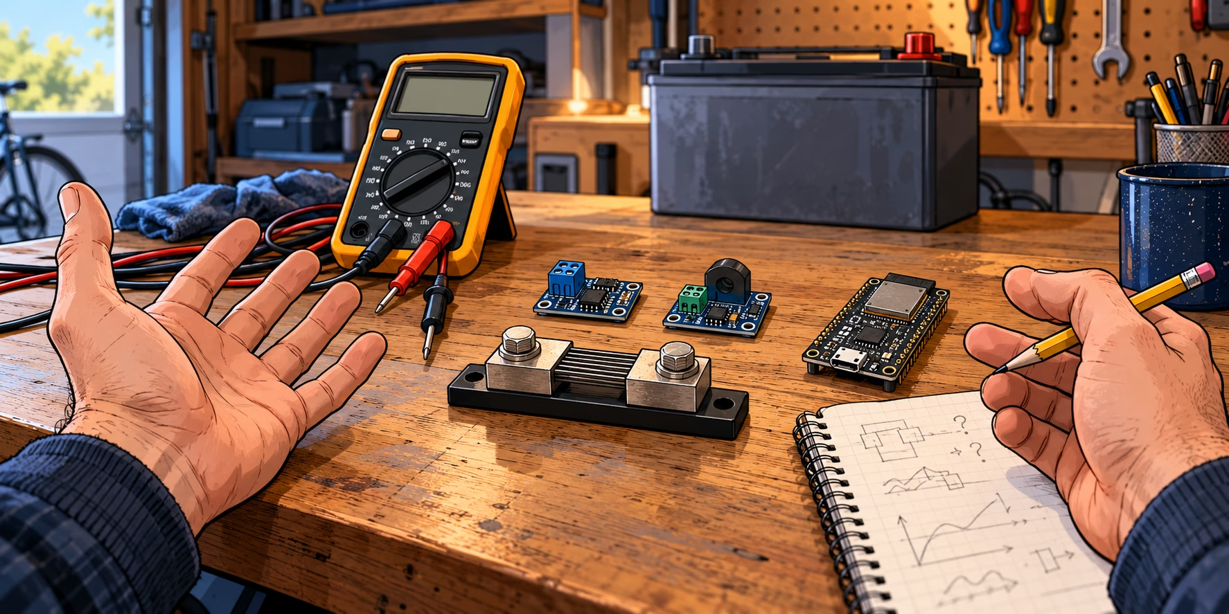
I wanted a battery monitor. Not a new research programme into the trustworthiness of tiny circuit boards. Just voltage, current and a sensible estimate of how much charge was left in the garage battery.
The ingredients seemed straightforward: a Renogy Core 100Ah battery, an external 200A/75mV shunt, an ESP32-S2 Mini and an INA226 module bought from Amazon. Send readings over MQTT to Home Assistant. Count charge in and out. Job done.
Instead, the first module disagreed with the multimeter. Its INA228 replacement then gave me a reason to stop before connecting any power.
A very small voltage doing a very big job
A shunt is a very small resistance in the main current path. Measure the drop across it, divide by the resistance, and you’ve got current. My external shunt is rated 75mV at 200A:
75mV ÷ 200A = 0.375mΩ
At 1A, the sensor is looking for just 0.375mV.
So I’m asking the little board to measure fractions of a millivolt. The heavy current goes through the external shunt, not through the sensor module. The charger and load returns need to be on the right side too, otherwise current sneaks around the shunt and never gets counted. (And this is just a monitor. The battery’s real BMS still handles protection.)
The plan was to count current in and out over time to estimate state of charge. But even a steady 0.5A error would add up to 12Ah in a day, which makes a pretty big dent in a 100Ah battery. I’d quite like the numbers to be right before trusting the percentage!
First hurdle: it was listening at 0x44
Naturally it didn’t work first time. My code expected the usual I²C address 0x40, but the module was sitting at 0x44. Once I had diagnostics that separated a failed read from a bad measurement, a bus scan found it.
0x44 is a perfectly valid INA226 address. There are sixteen options depending on the address pins, as shown in the INA226 datasheet. Annoying when it doesn’t match the library default, but hardly proof of a fake chip.
The registers came back with manufacturer ID 0x5449 and die ID 0x2260, which is what I’d expect from an INA226. Great, it’s talking… now to see whether it can actually measure anything properly.
Answers on I²C → identifies correctly → measures correctly
I’d got through the first two. One more to go…
Then the numbers stopped making sense
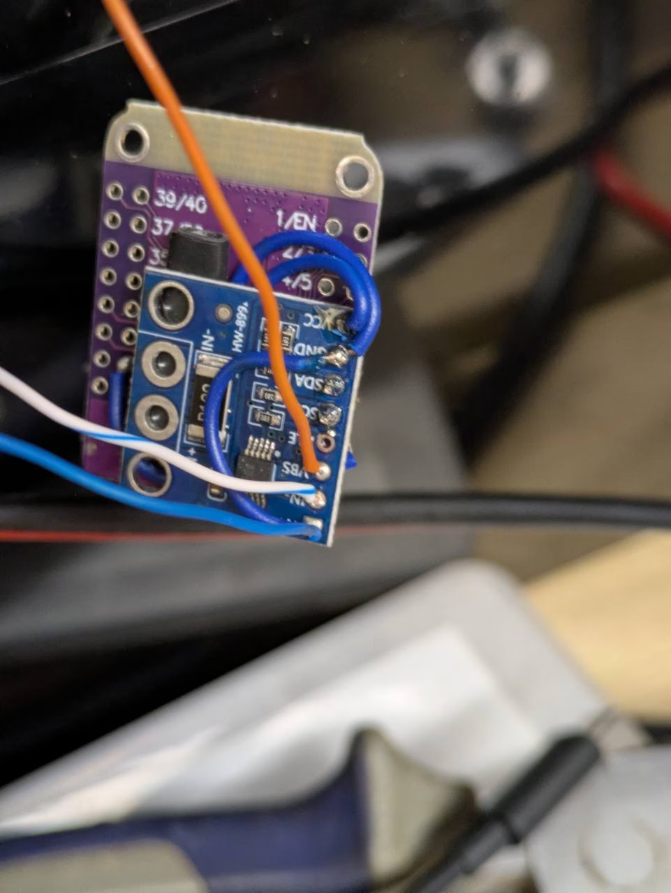
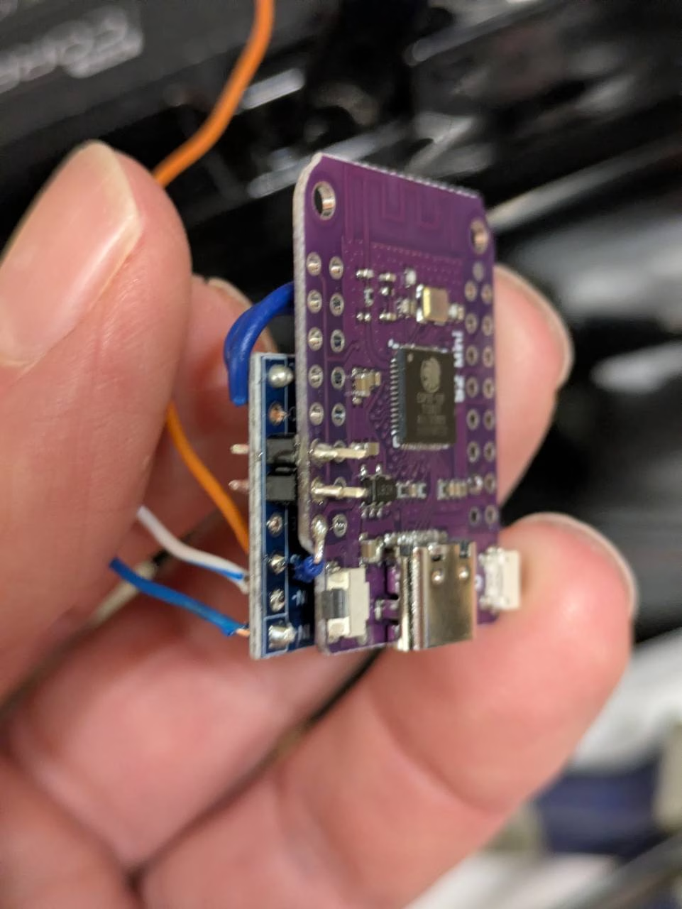
Once the readings started arriving in Home Assistant, the voltage was the obvious problem. I measured 13.24V at the INA, while the monitor insisted on approximately 13.95V. That’s not a rounding error!
Multimeter at the INA: 13.24V
Monitor: ≈13.95V
Difference: roughly +0.71V / +5.4%.
About 0.7V out on a 12V battery setup is a bit much. Before messing with calibration, I wanted to know why the board and meter disagreed.
The current looked suspect too. I measured about 0.4–0.5mV across the external shunt, which works out to roughly 1.07–1.33A with the configured resistance. One firmware reading was only 0.60A. The server load was moving around though, so those weren’t clean simultaneous measurements. I parked that question while chasing the voltage.
Later readings settled around 13.93V and 1.2A discharge, but that didn’t tell me which voltage to believe. Overnight it even claimed about 15.3V. With this sensor already looking dodgy, I wasn’t going to decide the charger had gone mad without checking the battery with the meter.
Why not just calibrate it away?
What about the R100 resistor still on the breakout board? That’s 0.1Ω. Put it directly in parallel with the 0.000375Ω external shunt and the combined resistance comes out around 0.000373599Ω, a difference of just 0.37% before allowing for sense wiring. That affects current scaling, not the bus-voltage measurement, so it wasn’t going to explain a 5.4% voltage error.
I could have chucked an offset or scaling factor into the code, but that would only hide the disagreement. Zeroing it with the server still pulling power would be even worse: I’d be teaching it that actual consumption was zero. So I left state of charge uninitialised rather than making up a percentage.
By this point I was thoroughly suspicious of the Amazon module. A dodgy clone? Maybe, but I hadn’t proved that, or got to the bottom of the accuracy problem with a controlled swap of the spare. Time to try an INA228 instead.
The replacement: an INA228 with a different surprise
The new INA228 breakout had a separate VBUS input and a little rear link joining V+ to VBUS. V+ here is a shunt sense input, not the logic supply. With my shunt on the negative side, that sense point and battery-positive VBUS need to stay separate. Before soldering anything, I got the meter out.
Between the pads labelled VBUS and GND: about 0.5Ω. Touch the probes together: also about 0.5Ω. Nothing was connected to the board, and the rear jumper measured open. Oh good… another mystery.
Labelled VBUS ↔ labelled GND: ≈0.5Ω
Shorted meter leads: ≈0.5Ω
I wasn’t connecting battery positive to that.
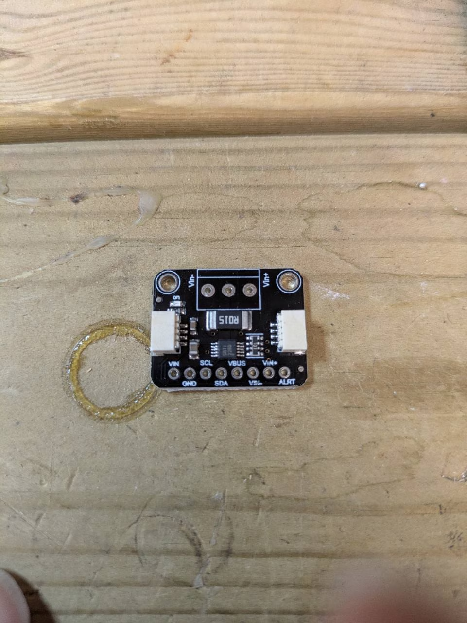
The INA228 datasheet describes VBUS as a high-impedance sense input in normal operation. An unpowered board reading the same as my shorted meter leads was enough to stop me going any further with it.
Was it actually shorted, or was a pad labelled wrongly? I hadn’t traced it back to a separate ground reference, so I couldn’t tell you which. Either way, I wasn’t keen to find out by wiring it to the battery.
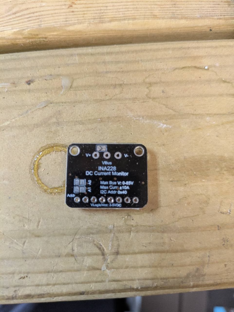
I’d already spent enough time on brand-new hardware that was meant to make this project easier. I decided to return it untouched. No cutting traces or unsoldering bits to repair somebody else’s board.
What I’m taking into the next attempt
- Buzz the board out before soldering. Unexpected continuity is much easier to deal with before everything is wired up. Do resistance checks with the power disconnected.
- Talking on I²C is only half the battle. A plausible ID register doesn’t mean the readings are right.
- Compare like with like. Same measurement points, steady load, same time. Otherwise it’s very easy to chase a difference you created yourself.
- Don’t zero out the load! And don’t let an unproven monitor make safety decisions for the battery.
So the code and MQTT side had made good progress, but I still didn’t have a battery monitor I trusted. Two boards, plenty of fiddling, a fair bit of swearing… onto the next attempt.
Leave a Reply